 |
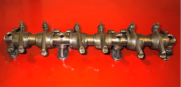
Front view of the 'A' front rocker assembly and pedestals. The oil
drillings in the ends of the arms can just be made out. |
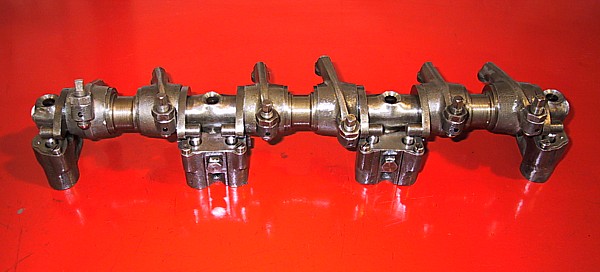 |
Rear view of the rocker assembly showing the eccentric arms sitting on
the tops of the plungers. As this engine has been converted to solid
actuation the eccentrics remain stationery and have no effect on the valve
clearances. |
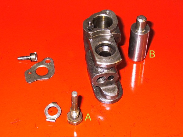 |
Rocker shaft outer pedestal. The bolt 'A' was the oil control valve
but has had its drillings filled with solder. The valve screws into
the threaded hole in the face of the pedestal which breaches the wall of
the vertical hole through which the retaining bolt passes. Oil is
fed up the side of the bolt to supply the hollow rocker shaft. 'B'
is a dummy plunger to replace the original hydraulic item. Originally,
oil leached through valve 'A' then via internal drillings into the plunger
chamber; the access notch being visible at the lip adjacent to the top-plate
locating pin. |
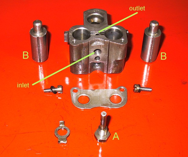 |
Rocker shaft inner pedestal. Similar in operation to the one described
above but operating two plungers. The dummy plungers 'B' are a press
fit in the chambers to avoid accidental alteration of the valve clearances. |