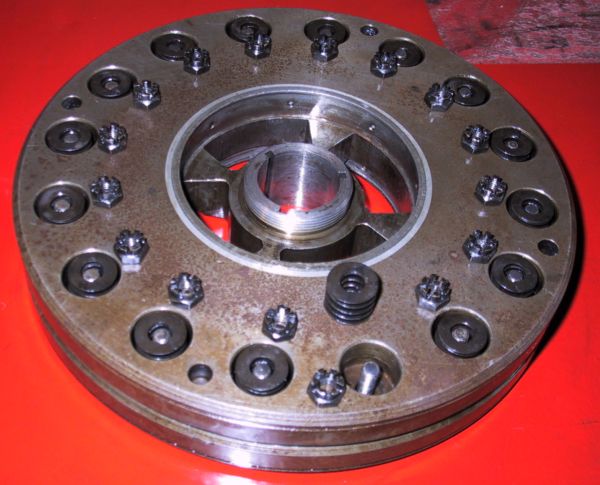
Flywheel section of the crankshaft damper unit ready for bolting together. The small holes visible in the centre are oilways for lubricating the moving elements.
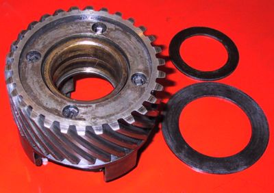
The crankshaft pinion which connects the crankshaft and its damper to the other timing case gears. This is a rear shot with the two fibre disks that bind the pinion against its rotating neighbours. The larger disk sits in the rebate at the back and rubs against the flange of number 1 main bearing whilst the smaller item goes in the centre of the forward face between the spring lugs (pictured below) and bears on the bush in the rear of the flywheel.
The 4 holes on the end face are where the set-screws for the front assembly are peened over. The large centre bush allows free movement of the pinion against the crankshaft.
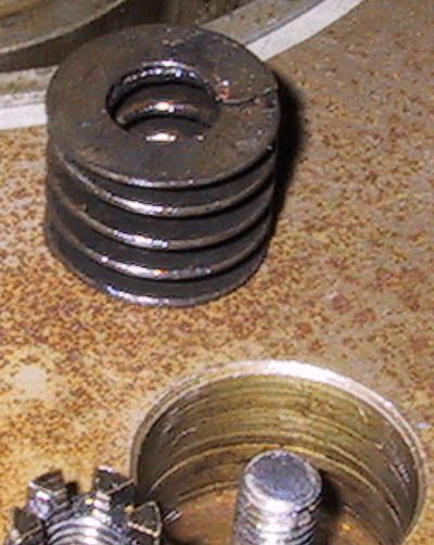
The indents in the side of the upright lugs are to locate the damper springs. The springs are in concentric pairs; the smaller diameter sitting over the centre pin with the larger outer spring being held by the rim of the hole. The following picture shows how the pinion is attached to the flywheel.
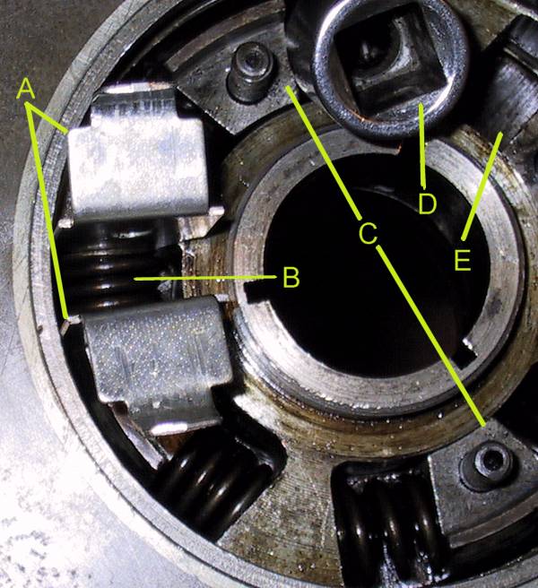
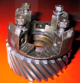
Front view of the centre of the damper. Lines 'C' point to 2 of the 4 lugs that protrude forwards between the 4 webs of the flywheel; a pair of springs sit either side of each lug pressing against the adjacent 2 webs of the flywheel - ie 8 pairs in total.
The 2 plates 'A' are odd scraps of metal used as guides to compress and insert a spring pair ('B') into their cavity. As one pulls out the plates it is most important to check that the inner spring sits properly over the centre locating boss as it is very easy to trap this spring and bend it out of shape.
'D' is a socket used as a spacer to hold the relative positions of the pinion and flywheel whilst inserting each spring set. It is necessary to instal the springs alternately for clockwise and anti-clockwise deflection to reduce the effort of re-aligning the two moving elements.
Cavity 'E' is an unfilled spring position.
Once installed on the crankshaft the damper is locked in place by a notch nut that tightens against the end face of the centre tube (with the 3 Woodruff key slots). The 4 studs at the outer ends of the pinion lugs, 2 of which are shown a 'C', are used to attach the starter dog over the nose of the crankshaft. The flange on the starter dog also acts as a clamp to hold the pinion and flywheel in correct radial alignment.