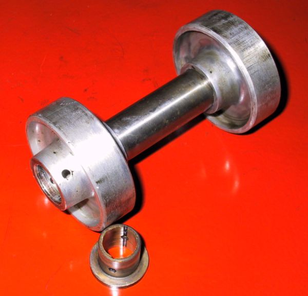
Here is the 'B' side (near side) spacer for the distributor drive cross-shaft following a good clean-up. There are several IMPORTANT matters to note with these spacers :-
- the 'A' & 'B' side spacers are different (see below) in that the 'B' side has only one bush, on the outer side, due to the centre gear locknut.
- EACH BUSH has two drilled oil holes with an axial channel - and they locate in the spacer with these holes at a 90 degrees offset from the holes in the spacer nose. There is an oil channel machined radially in the spacer to allow gentle oil flow onto the x-shaft.
- All 3 channels and outer holes were completely blocked when this engine was dismantled. It is, therefore, IMPERATIVE that the bushes are knocked out and all parts are cleaned prior to re-installation.
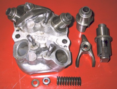
One of the other cleaning jobs for the day was a cam follower block assembly ( #4 as it happened). This is a partly assembled unit with the relevant components on show. The guides are a light press fit in the aluminium casing.
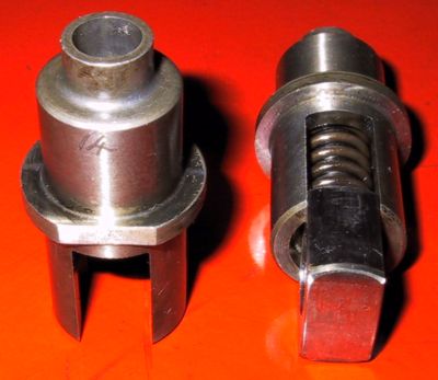
Two follower guides; one with the follower, washer and spring inserted. The number 14 can be seen engraved on the left hand guide - whoever worked on this engine in the past engraved EVERY component so that its location could be established. Even numbers related to the 'A' side valves - so this is the forward guide to the fourth block on the off side. Note the flat face on the lip, that is an accurate fit against a flange on the block , which stops the guide rotating in its seat.
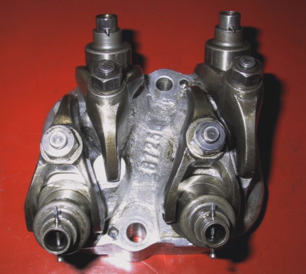
Pictured here is the re-assembled block with the four cam followers depressed against their springs and pinned up using panel pins through the oil holes. This method will ensure that the block can be seated properly in the cam chest without fighting the spring pressure.
Spot the deliberate mistake! The pins should be (and have been changed to be) inserted from the inside to avoid difficulty in removing them after the blocks are installed.