 |
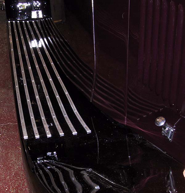
The running boards are formed by a wooden structure attached to the chassis brackets. The aluminium covers rest on the wooded substructure. The tread strips are attached by screwing them through the aluminium and into the wooden supports beneath. This photograph shows the first six strips in place. The rear edges are fitted so that there is just enough clearance to allow fitting of end caps that will line up with the rear joint of the wing and running board. The front edges are offset to give a slight angle such that, with the end caps in place, they will form a natural angle that meets the junction of the rear bonnet edge. |
 |
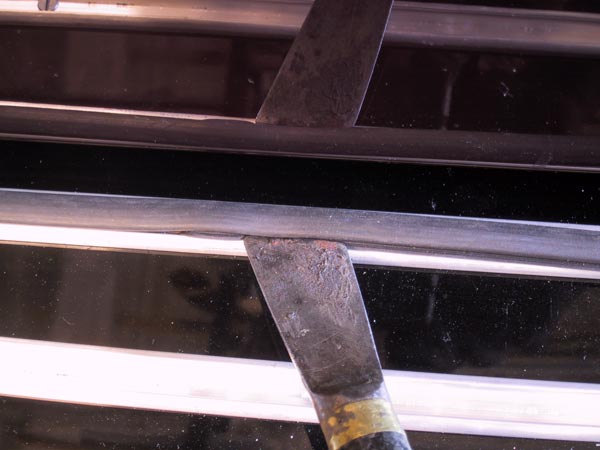
The rubber inserts for the tread strips have a cross-section shaped like the Greek letter Omega. Installation is quick and simple. The one lip of the rubber is hooked into the aluminium strip and the other lip is eased into the channel with a blunt, flat blade. The rubber should be cut to a length roughly 2 or 3inches longer than the channel to which it will be fitted. The excess length is accommodated by compressing its length into the channel along the length of the host material. This will ensure that the rubber is a tight fit and that shrinkage, due to temperature or weathering, does not lead to the insert eventually appearing to be too short. |
 |
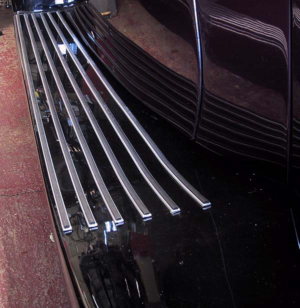
The first set of rubber inserts in place. Note that the ends of the aluminium channel have been cut and folded so that there is a positive end-stop to prevent the slightly compressed rubber from 'creeping'. |
 |
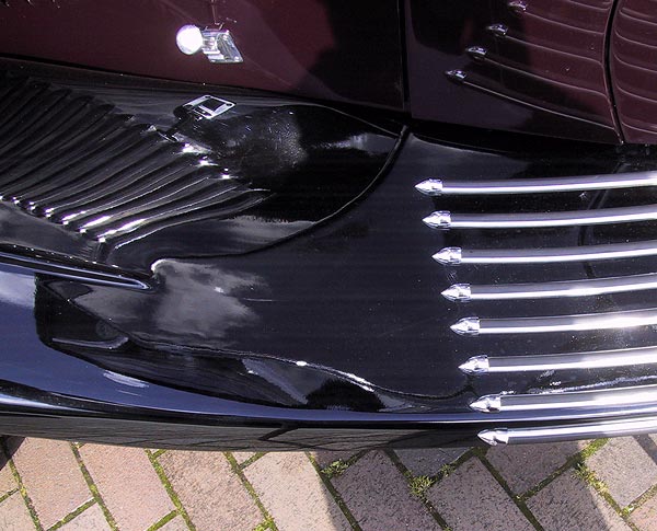
The finished job. There are seven strips on the upper face of the running board plus one on the vertical, outer face to prevent the inevitable car park dents. The end caps used on this car were cast, chromed brass with countersunk fitting holed and an interior butt-stop to prevent the rubber from climbing out of the channel ends. |