 |
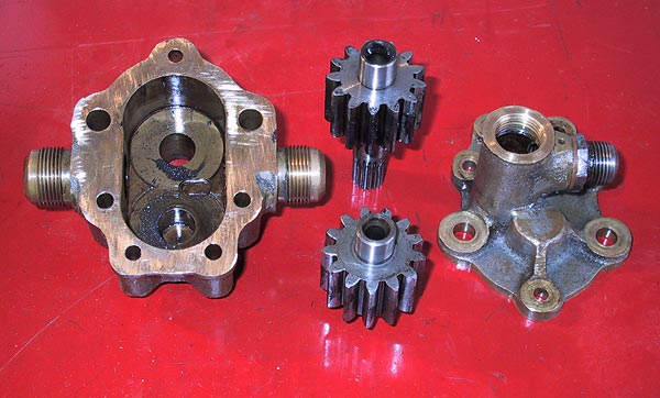
The oil pump main components. The original tolerances are shown below with the final figures for this pump shown in parenthesis: - gear backlash = 0.003" (0.013") radial gear clearance = 0.002" (0.005") gear end float = 0.002" (0.002") drive shaft radial clearance = 0.0005" (0.0005") Contrary to what is stated in Haynes & Grigsby the General Arrangement drawings show that there is no paper gasket used on the bronze bodied pump. |
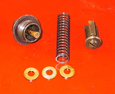 |
The oil pressure relief valve in pieces. The spacers fit over the pin in the threaded cap - a maximum of 5 spacers may be used. The correct running oil pressure is18psi at 50mph with a hot engine. |
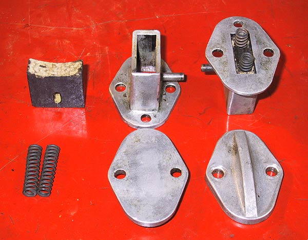 |
The two brake assemblies for the dynamo drive pinion. The shaped fibre shoes should be a tight sliding fit in their cases. The movement range of the shoe is restricted by the cross-pin in the slot of each shoe. |
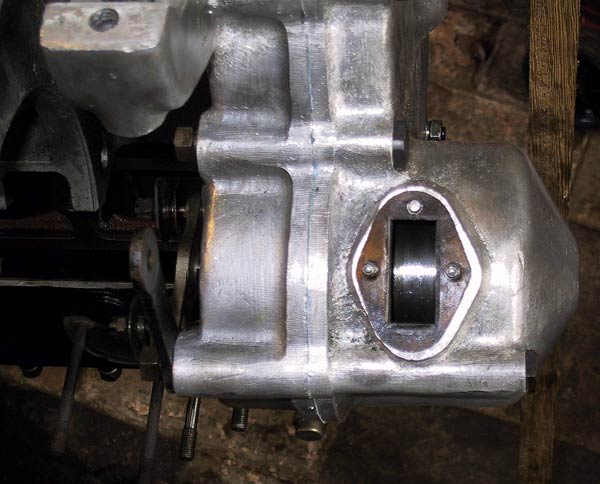 |
Aperture for the brake assembly showing the drum on the back of the pinion. |
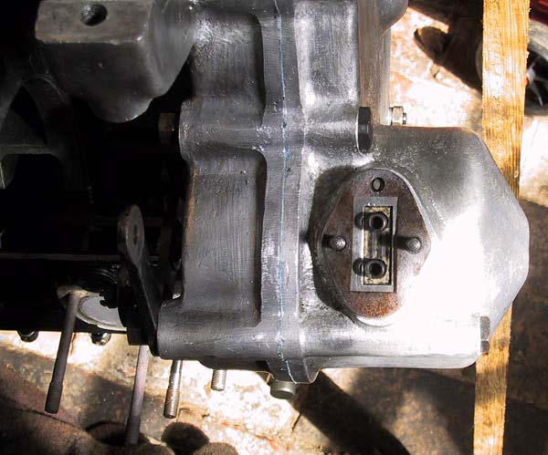 |
Two gaskets are used on the casing; one above and one below the flange. New shoes and springs were fitted. The previous shoes had swollen to the point where they would no longer move in the casings. |
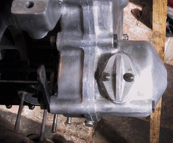 |
The lower brake fitted and bolted down. |