 |
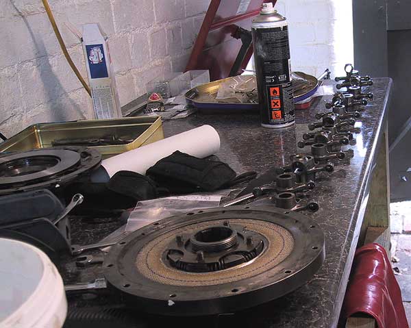
The rocker assembly needed stripping and cleaning. |
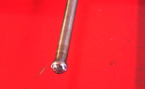 |
The push rods all displayed signs of wear on the lower ball-end. The picture shows a small nipple worn by the drilling in the adjuster socket. These nipples were removed by gentle application on a whet stone. |
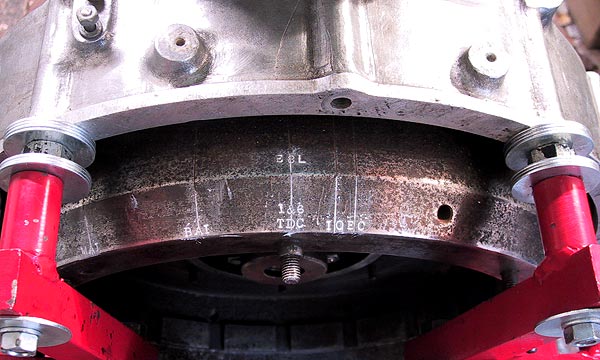 |
Flywheel markings highlighted ready for damper installation. The pointer for alignment sits on the centre line of the middle bolt hole - shown centre. The markings are, from the left: -
|
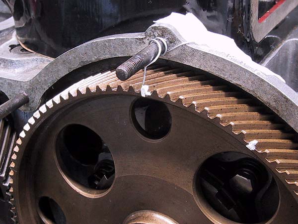 |
The push rods and rocker shaft were installed. All tappet adjusters were left slack except #1, which was adjusted to 0.020" gap as specified on the flywheel. The camwheel is rotated anticlockwise until the #1 push rod starts to close the gap. The camwheel is adjusted so that the push rod can just be rotated between thumb and forefinger. A wire pointer is fixed to point at the camwheel teeth: the appropriate tooth being highlighted. The camwheel is then rotated clockwise by two teeth to compensate for the helical offset of the damper pinion. The crankshaft is adjusted so that the IO marker is aligned with the rear pointer. The rear section of the damper is offered up with the splines in line with the crank; the cam is rotated as the damper is engaged with the splines and camwheel teeth. |
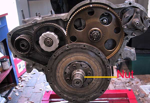 |
Care is required to avoid dislodging the friction disks. Note that the spacer is placed over the 4 centre bolts and the nuts are attached to stop the bolts falling out. When the pinion is fully engaged with the camwheel the locknut is temporarily attached. The flywheel should then be turned back by about 180 degrees and then carefully advanced to check the TDC and IO positions. If the correct teeth have been engaged the #1 push rod should just start to tighten as the IO mark is reached. When satisfied with the set-up the lock tab washer and serrated nut should be installed, tightened and bent down. |
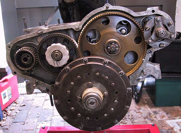 |
The spring-loaded front ring and the front half of the damper are fitted, taking care to not dislodge the friction rings. The 4 centre and 12 peripheral nuts and bolts are tightened using lock tab washers to secure them. |