 |
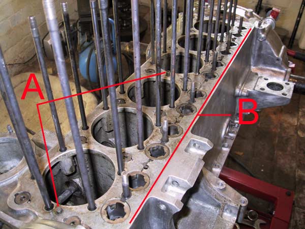
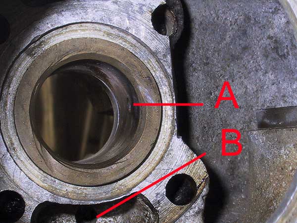
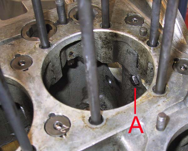
After a preliminary clean of the block-mating face there are several points of note. 'A' points to the two dowels that centralise the cylinder block on the crankcase. 'B' shows all of the tappet guides, block studs and the oil channels that feed the camshaft bearings. A close-up is in the next photograph. |
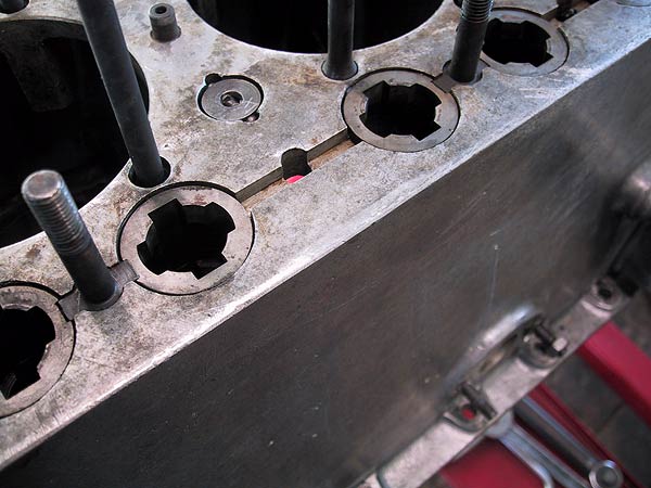 |
Note that the short block studs, which also act to hold the tappet retaining bridge pieces, have shoulders that stop the guides rotating. The upper faces of the guides are slightly lower than the block face. The following picture shows the inside view from underneath. |
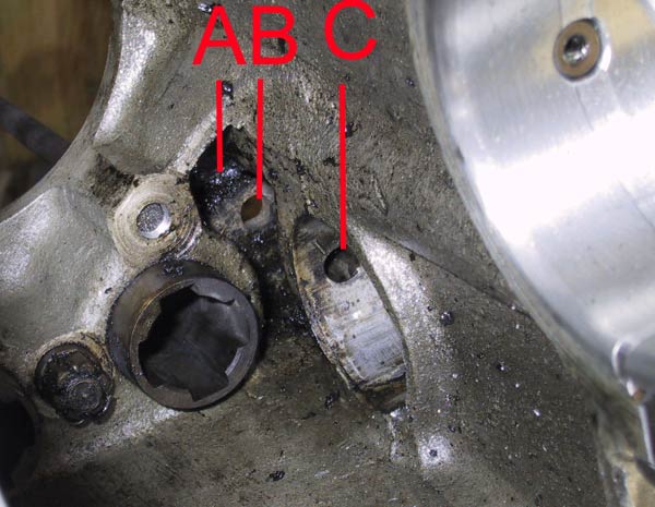 |
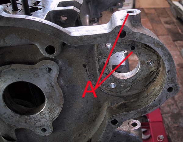
Looking up, from under the engine, hole 'B' is the drilling in the centre of the channel between the guides. Hole 'C' is directly below 'B', and is the dowel hole in the cam bearing support. 'A' is the upper cavity above the cam bearing housing. The cavity passes above the cam housing, being accessible from either side in numbers 2 through 6. All of these cavities, which are about 1.5" deep, appear to have collected 70-odd years' worth of sludge and other unwelcome debris. |
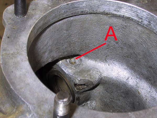 |
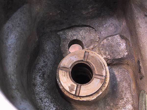
Looking down through the distributor mounting hole. The bush is for the water pump drive shaft. The hole 'A' is a drain into an annular groove in the outside of the bush. See the next picture. |
 |
'A' is the oil feed hole for the water pump drive shaft. If there is any restriction in supply it would be necessary to remove this bush for rectification. Fortunately, the passages are clean in this engine. Hole 'B' is the return drain for any oil that bleeds along the water pump shaft to the rear of its housing. Behind the bush is a gap of about 1/16", between it and the rear cover plate, in which oil is collected and returned to the timing chest. If this hole becomes blocked there will be a significant oil leak at the rear of the bush. The only way to clear the drain is to strip the timing cover and remove the drive mechanism. |
 |
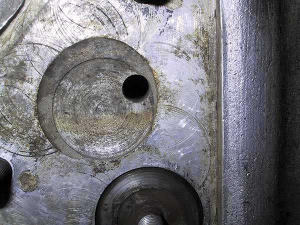
The upper bush for the shaft that drives the distributor and oil pump. The large hole is the drain directly back into the sump. Note the wear on the upper flange of this bush. The spur gear that is driven from the back of the water pump drive shaft should be shimmed to give a back lash of about 0.003". When dismantled, there was no shim and the back lash was about 1/8", which probably accounted for some of the tick-over clatter and an inability to get a smooth engine below about 500 rpm. This problem will obviously be rectified when re-assembled. |
 |
This is the oil supply to the idler gear shaft. Behind the drilling is a small trough which collects oil from splash in the sump and lets it run onto the gear axle. The disc and stud, at the bottom of the picture, are the front blanking plate to the oil gallery pipe. |
 |
The dynamo bearing is pressure fed as part of the rocker shaft oil supply system. Oil is delivered to the top union and exits just above the axle for the pinion. |
 |
This bolt is one of the fasteners for the idler gear axle bracket. Its end had been peened over the nut so was damaged during removal; it will have to be replaced. This exercise must be done before the block is attached because the cylinder extension will cover the bolt head. |