 |
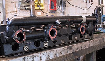
Inlet side of the 'B' head showing the inlet the manifold
below the water jacket. This is a useful aid for remembering which
bolts go where. |
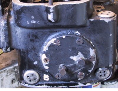 |
This picture shows the front end plate - the rear plate is similar but
without the two bolts used for attaching the HT lead conduit. Note
the small 'B' stamped on the front face of the casting to denote which head
it is. |
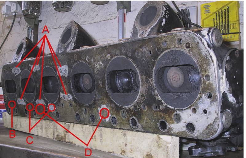 |
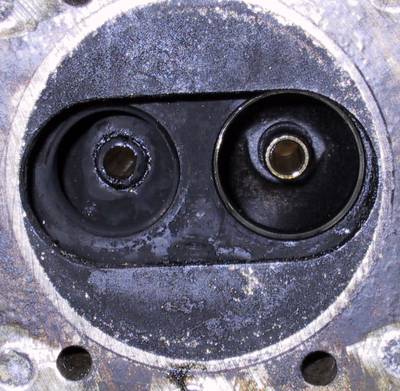
An interesting conundrum shown above. The front of
the head is to the left of the picture. Having scraped off some
of the gasket sealant from the mating face the positions marked 'A' and
'C' are NOT drilled through the head casting even though they sit above
water passages in the block. This lack of water access is presumably
to force the water flow to the rear of the head. Position 'B' (front)
in the picture is drilled to mate with the water passage in the
block. The two positions marked 'D' are quite large holes in the
head that have been blanked-off with brass dowels - possibly needed for
internal machining during manufacture.
The 'A' head is a mirror image of above. Of the four heads in my
possession three are as shown above but the fourth is drilled through
the head at all points 'A' and 'C'. When drilled as in the fourth
example these heads are interchangeable. |
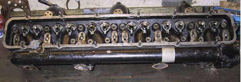 |
| Viewed from above. and with the valves
removed, one can see the inverted conical seats in the upper faces of the
valve guides. Four oil passages, used to feed the rocker assemblies,
can be seen in the pedestal platforms for numbers 1,4,5 & 8 (just below
the stud holes). |
 |
To the left is a close-up of two valve seats and the inner ends of the
guides. The blackened seats are due either to poor tappet adjustment
on my part or it was caused by carbon leaching down when the heads were
soaked in derv for several weeks. There is no pitting on the seating
surfaces of head or valves. |
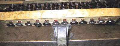 |
Above is my way of keeping the valves in the correct order. A piece
of 4"x2" soft wood with two rows of 12 holes and the outer edges
stamped with relative positions. Small pieces of plastic tube are
inserted under the valve head to give finger tension on the springs / collets. |
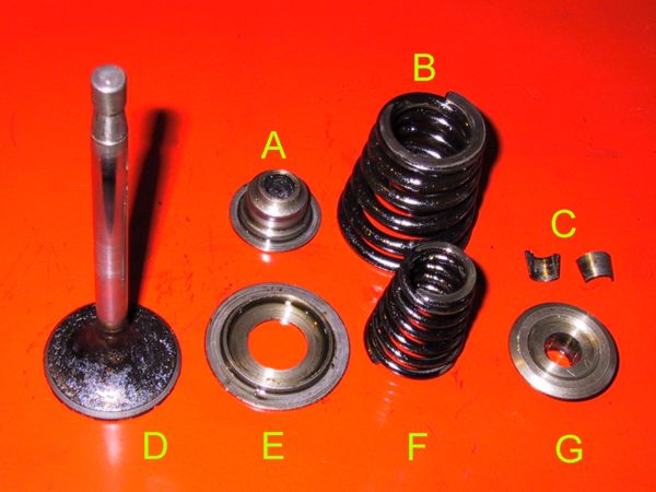 |
The valve components for the A, B & C series engines;
D series had single springs, solid tappets and a different camshaft profile.
A - The cap containing the valve seal
B - The outer spring
C - Split collet
D - Valve
E - Locating escutcheon for the seal cap (A)
F - Inner spring
G - Spring retaining cap |