 |
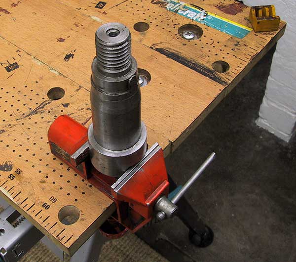
Slipper flywheel damper mandrel. The centre disk is locked from rotating by the 2 lugs machined into the collar just beneath the thread. |
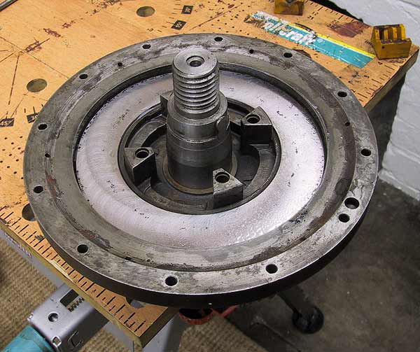 |
The rear element of the flywheel. The friction face has been ground to give a clean surface. The absolute minimum of metal was removed. |
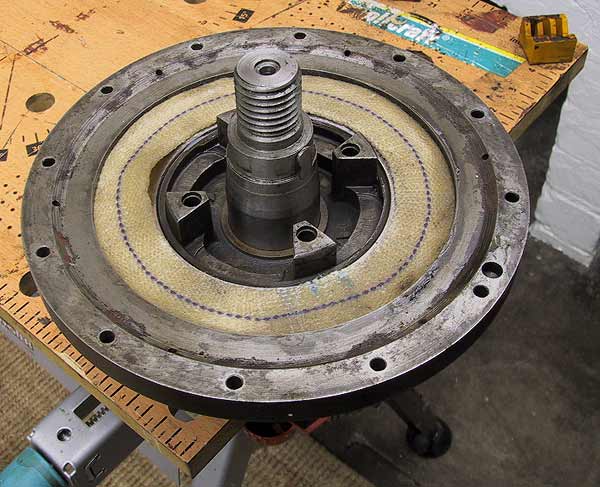 |
The rear cotton washer in place. The washers had spent 3 days in a specially designed clamp to ensure correct and uniform compression. |
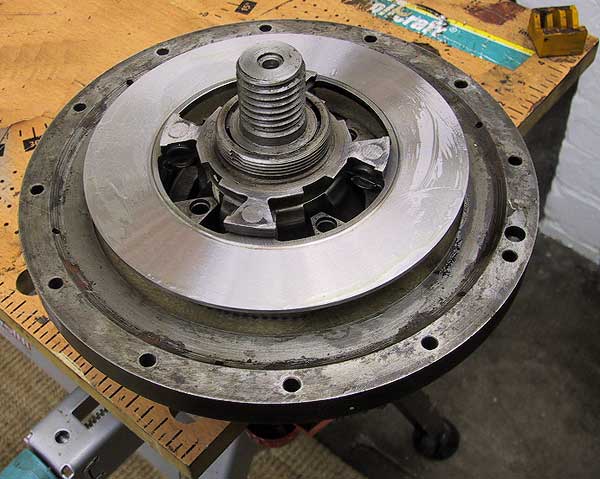 |
Centre disk on the mandrel. |
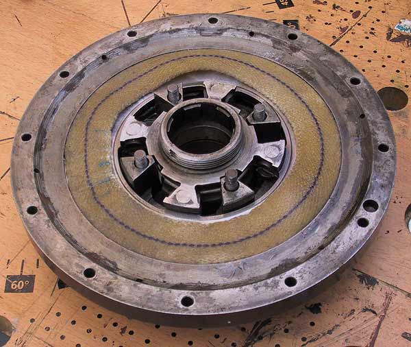 |
For illustration purposes the assembly is removed from the mandrel and set on the bench. It will be noted that the second washer only just fits in the remaining rebate in the rear element of the flywheel. The flywheel is mounted on the mandrel at this point. The mandrel nut is locked into place so that the centre disk will not move. |
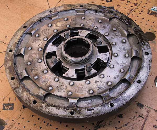 |
Care is needed to make sure that the friction face of the diaphragm does not pinch the washer. There is a spacing plate that sits over the four bolts before the from of the flywheel is attached. Every piece of the flywheel is stamped with a location marker. It is important that each stamped mark is lined up against the others during assembly. |
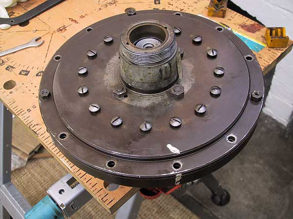 |
The front face is installed over the locknut. The 4 central fasteners and 10 of the12 peripheral ones are attached. |