Rolls-Royce 20/25 - connecting rods
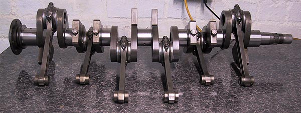 |
As received from the machine shop. Everything comes with a warning that it requires stripping and cleaning properly. |
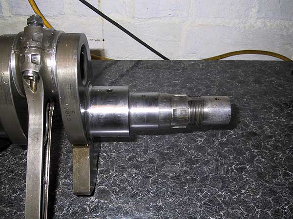 |
Crankshaft nose showing the complicated machining work to support the front main bearing and crankshaft damper. |
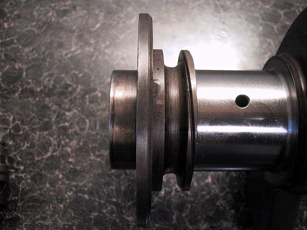 |
The rear of the crankshaft showing the flywheel flange, oil scroll and #7 main bearing journal. |
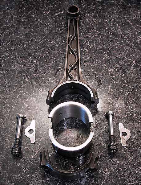 |
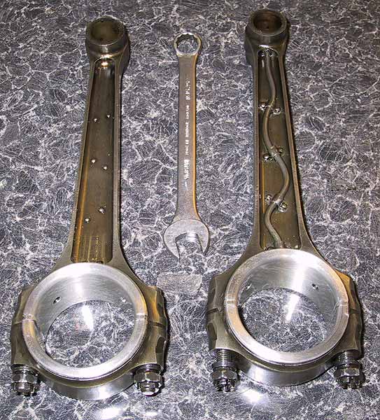
A dismantled con rod showing the shells and shims. The upper shell-half has 2 holes that allow oil to flow up the feed pipe to the little end bush. The latter has 6 feed holes fed from a groove in its outer face. Later con rods were drilled to provide the oil feed; the external pipe being rendered unnecessary. The shims, which are faced in white-metal, have a nominal thickness of 0.100". It is necessary to pre-assemble each rod and bearing in order to check the bearing nip. Instructions are in the manuals (to save retyping here) but the point being that nip must be adjusted until the correct setting is achieved. Failure to accurately set the nip will more than likely lead to rapid bearing failure. THERE IS NO SHORT CUT. Note: - Altering the shim thickness has no effect on the nip of the shells in the rod but does affect the fit of the rod on the journal. To increase the shell nip the joint face of either the rod or the cap needs to be reduced. To decrease the shell nip the butt face of the shell needs to reduced |
 |
Showing both sides of the early type of con rod. It is important to verify that the pipe is clear and clean, the soldered joints are secure, the pipes are not stress-fractured and the retaining rivets are still tight. The little end bushes should be checked for wear. The oil drillings should be tested to ensure that they are unblocked. The rods should be inspected for cracks, straightness and twist. |
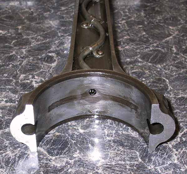 |
Oil pipe entrance. The shadow in the metal is where the oil passes behind the upper shell-half. |
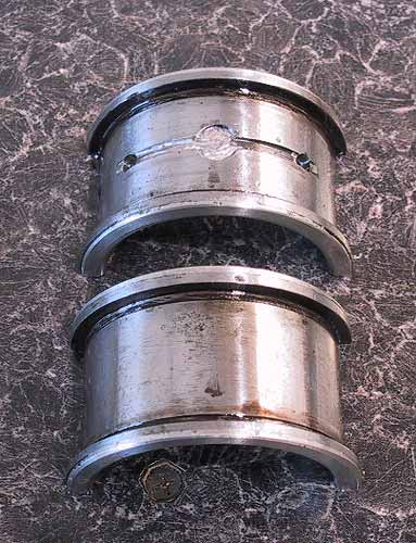 |
Upper and lower shell halves; the former showing the oil groove. There is a radiused rebate behind each flange (showing as a black line in the photograph). |
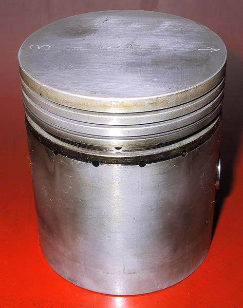 |
A clean piston showing the thrust side with 4 oil holes. On the relief side there is a slot of the same length as the gap between these outer holes. This piston type has no split in the skirt. This design was prevalent during the 1970s/80s. Manufacture has reverted to the split skirt design in recent years. This engine is having a new cylinder block installed so it will be necessary to fit new piston rings to aid running-in and gas-tight operation. |
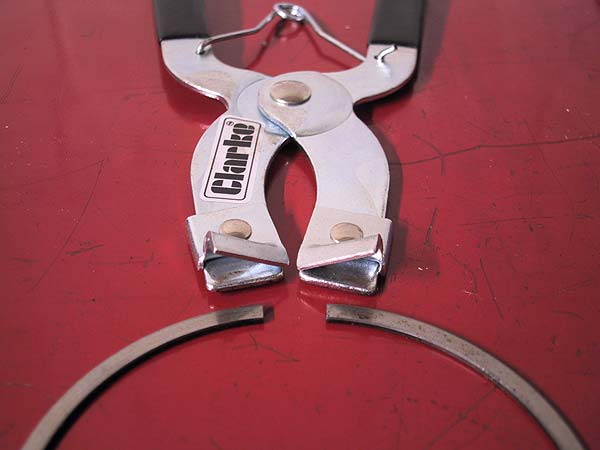 |
Simple and cheap - piston ring pliers make the job so easy. |