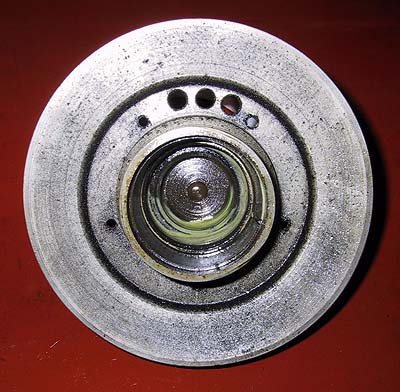
The locking plate removed from the pulley.
As this engine was built after GKT21 the serrated nut on the pulley can be ignored as far as the removal process is concerned.
(On engines up to chassis # GKT21 the serrated nut (L/h thread) must be removed prior to the release of the dog-nut and pulley.)
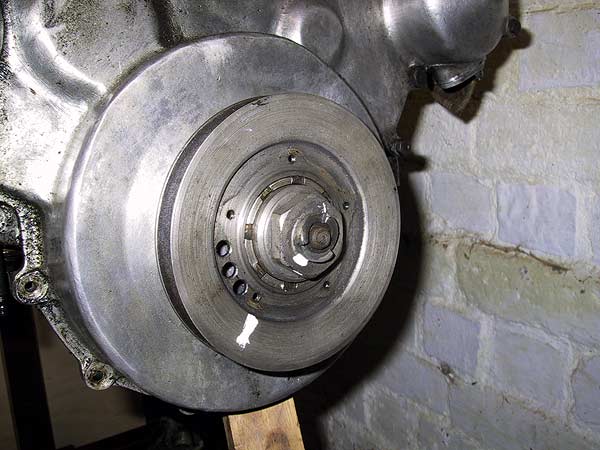
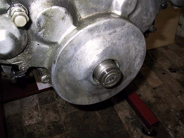
Sprag the crankshaft, to stop it rotating, then remove the starting-dog nut, which is right hand thread.
As soon as the nut is loosened it can be unwound by hand. The pulley and boss withdraw to expose the oil-screw.
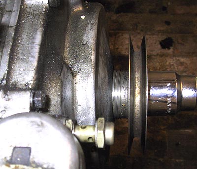
A shot of the rear of the pulley showing the taper and key slot (at 4 o'clock).
The nose of the crankshaft showing the thread to which the starting-dog nut is attached. The central pin and slot is the end-cap of the front sludge trap.
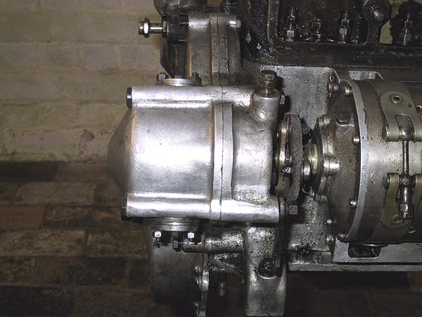
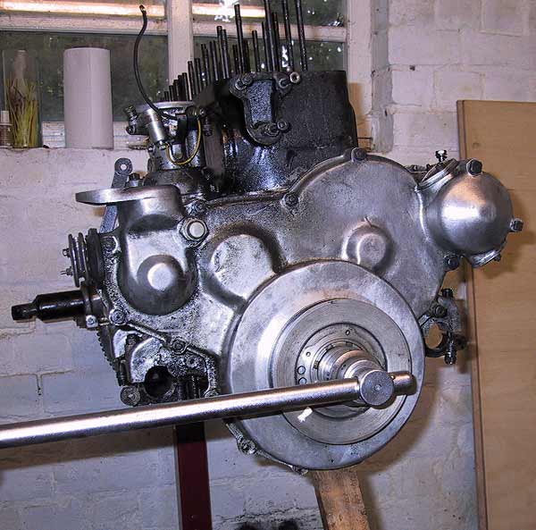
Front left hand side of the engine showing the dynamo drive housing. From chassis GHW19 the revised dynamo drive system was fitted with two spring loaded brakes. The the housing lids are visible, above and below the main casing, each held in place by two studs and nuts.
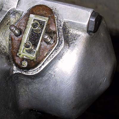
When a housing lid is removed it exposes the top of a fibre brake shoe into which are inserted two pressure springs.
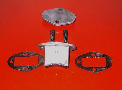
The brake assembly is a sliding fit in the casting. The paper gaskets fit either side of the flange of the brake block housing. The brake should slide inside the housing.
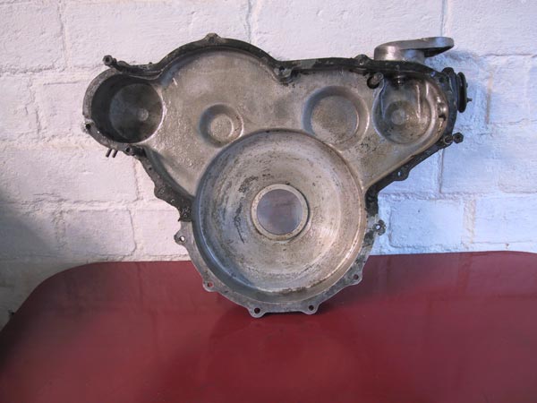
Inside the wheel case cover. The odd-shaped casting, top right, is the mounting base for the ignition coil.
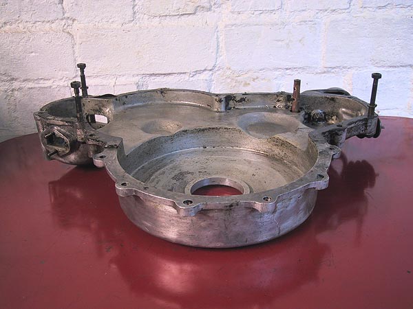
A different view of the wheel case cover showing the oil supply pipe to the gear train - inner right of the picture. The three fasteners are all register bolts to ensure accurate location of the cover to the crankcase. The register bolts have enlarged diameter shanks that mate with reamed holes in the crankcase flange.
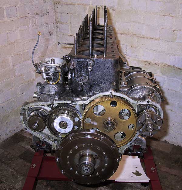
The crankshaft damper is centre-bottom. From left to right are the water pump pinion, idler gear, cam wheel and dynamo pinion.