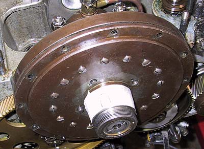
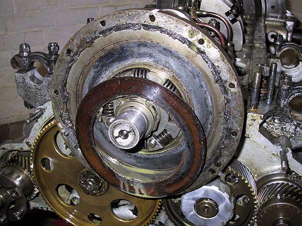
This is the Low Inertia crankshaft damper introduced at chassis #GKT22.
First step in the removal process is to remove the peripheral fasteners plus the 4 nuts adjacent to the central hub. All nuts should be locked by tab washers.
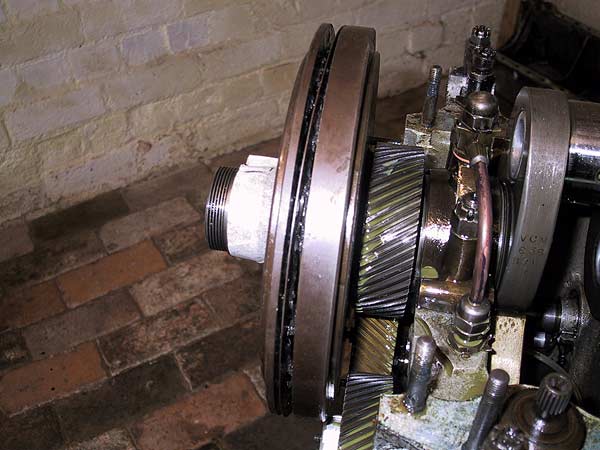
With all nuts and bolts removed the front face and front pressure plate should slide off the nose of the crankshaft.
This is the front pressure plate after removal of the front of the damper. The pressure marks from the 16 springs are clearly visible.
Note the outer ring of solidified oil debris that has built up. There are 12 drain holes interposed between the peripheral clamping bolts; all of them were clogged up.
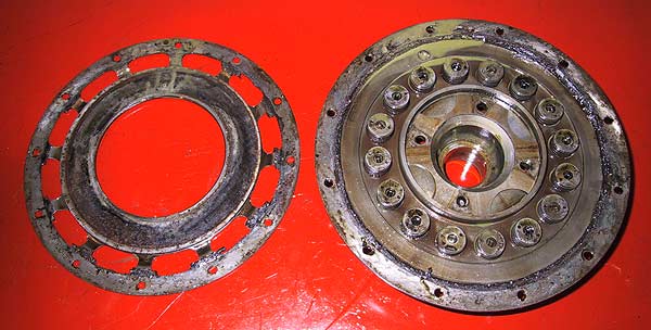
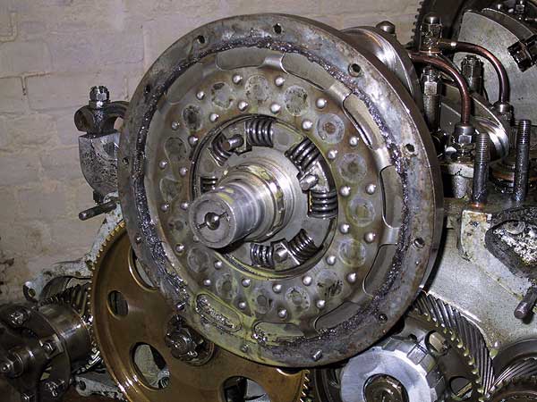
On the right: - the inside of the front plate from the damper showing the 16 springs. Note the cross-shaped spacer in the centre of the hub.
On the left: - the front pressure plate showing the wearing surface that abuts the friction ring.
The friction ring. In this engine the cotton duck material had been replaced with some form of fibre disc. Its efficiency appears to be no better than the cotton because it has rusted to the centre-disc. The dark patch on the centre-disc at 11 o'clock is the adhesion point.
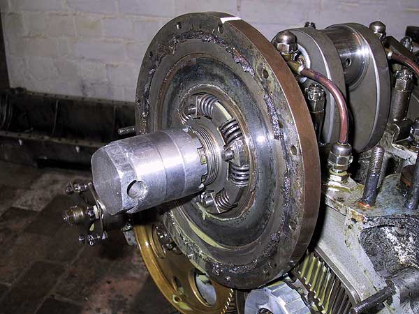
Note the serrated nut, on the nose of the crankshaft, that holds the damper onto its taper. The nut is held by a tab washer with two tangs.
Tool number R2883 for releasing the serrated damper nut (right hand thread).
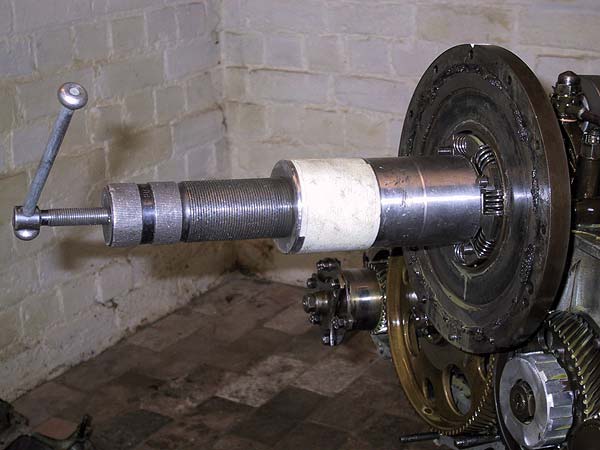
A modern version of tool R2879, the damper extractor, which is left hand thread.
Care is required when using this tool. Release the pressure as soon as the taper grip has broken; the damper must be removed by winding it off the gear teeth.
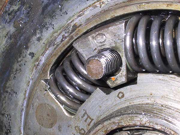
Close-up shot of the hub centre. Note the twin concentric springs used to transmit power from the driven centre-plate onto the hub pinion.
All elements of the damper assembly are stamped or engraved 'O' to mark relative positions when re-assembling.
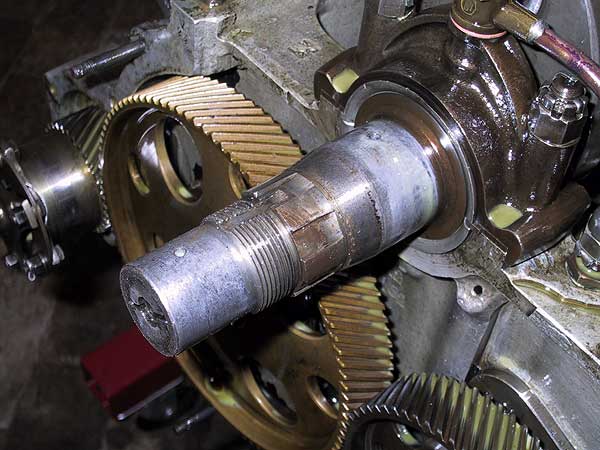
The crankshaft nose, following the removal of the damper, showing the coarse keyways used to locate the driven element inside the damper.
There are two radial oil drillings visible on the crankshaft nose: there are 2 others on the opposite side.
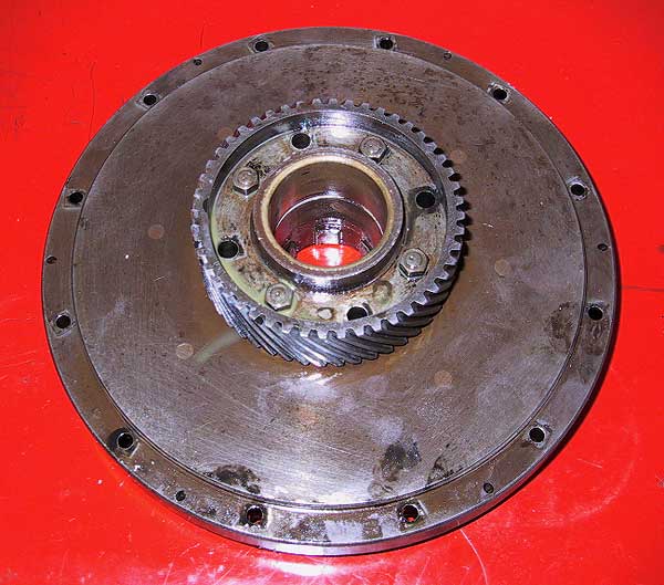
Rear view of the damper. The pinion is an integral part of the rear body in this design. The keyways for the centre driven element are visible inside the bore.
The 4 holes in the pinion face are for the bolts that help hold the two halves together.
It should be noted that the rear friction ring cannot be released until the centre-disc is removed. This is achieved by extracting the hub springs and will be shown later.