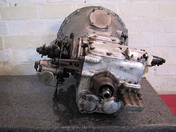
Rear view of the gearbox. The selector rods case can be seen rear, bottom right adjacent to the output shaft.
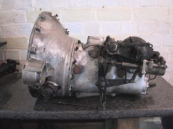
Nearside view showing the brake servo - a close-up is lower down. Note the brake release damper, middle right, which is attached to the top of the 'T' connector. This over-engineered piece of kit was designed to stop the whole assembly clattering when the brake pedal is released. It is important to keep this unit clean and lubricated (see the One-shot oil supply).
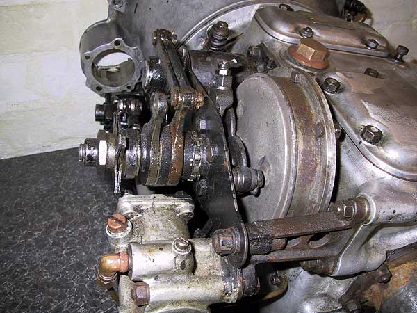
Close-up view of the brake servo.
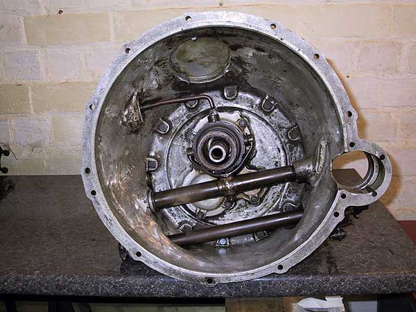
Inside view of the bell housing. Note the oil pipe, top left, that drops oil into the well on the top of the release bearing trunnion. The two horizontal shafts beneath the release bearing are the clutch cross-shaft (upper) and brake shaft (lower). The circular casting extension on the right of the picture is for the starter motor.
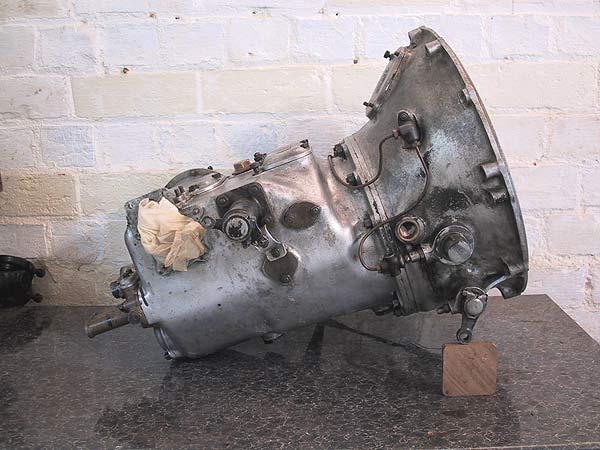
The offside of the clutch cross shaft, where it exits the bell housing, has a Woodruff key for locating the pedal shaft. The paper bung is to stop dirt ingress via the gear stick aperture.
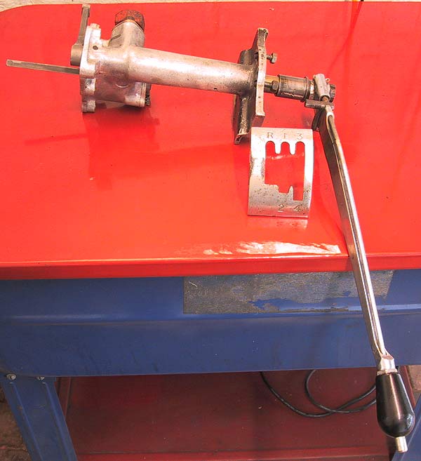
The gear stick extension arm and gate.
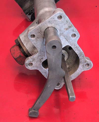
The selector arm at the inner end of the gear stick cross-shaft.
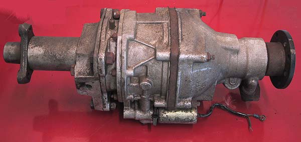
The Laycock 'J' type overdrive unit. This provides an engine speed reduction of roughly 27% in 3rd and 4th gears.