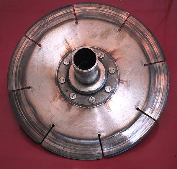
The clutch driven disc - gearbox face. Unlike modern assemblies, the Small Horsepower Rolls-Royce clutch (with the exception of the last 42 chassis) had the friction rings attached to the flywheel and pressure plate. Each 'blade' on the driven disc is displaced from its neighbour, fore or aft, by 0.025" - the purpose being to give a degree of spring to assist on smooth engagement.
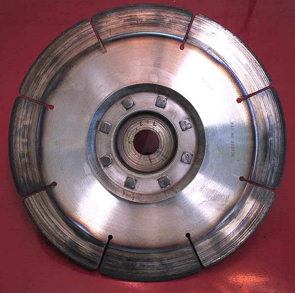
Same disc but looking at the engine face. The number on the centre boss is E6L, being the correct and original part number for this engine, #E8L.
The rubbing surfaces are slightly scored but are within tolerance so the disc will be re-used. The small areas of 'bluing' were caused when the clutch started to slip. The car was not allowed to proceed with a slipping clutch, which saved the disc from heat distortion.
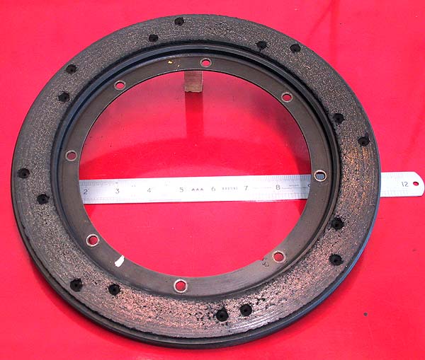
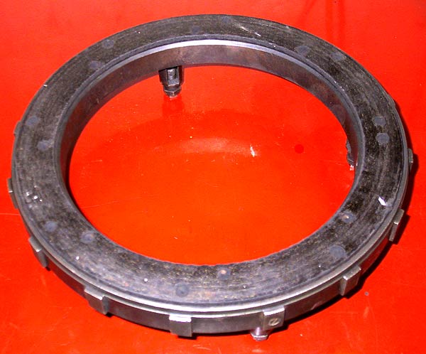
The friction ring carrier that attaches to the flywheel. There was no evidence of oil contamination or glazing on the wear surface. Friction material thickness was 0.175", which shows only nominal wear compared to the original thickness specified at 0.187" (+0.010").
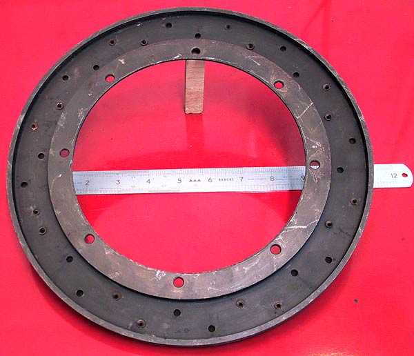
The rear face of the flywheel carrier ring.
The pressure plate carrier for the friction ring. A poor photograph. The surface compares to the flywheel side. Thickness was 0.170"; again showing only nominal wear.
So why was the clutch slipping?
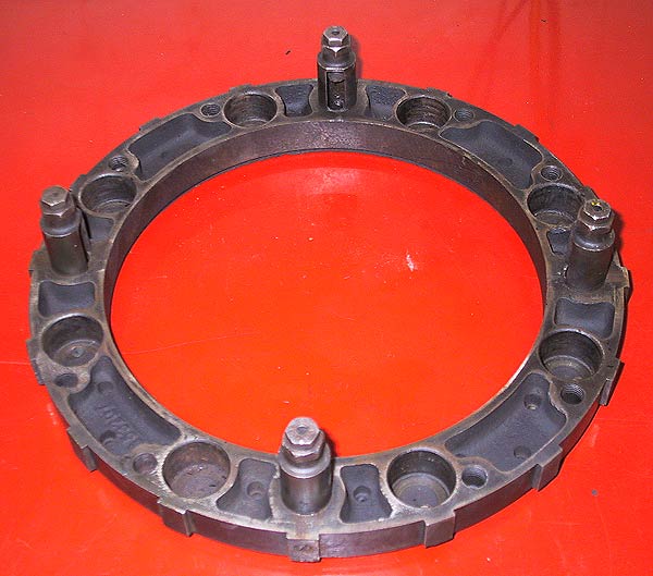
The reverse side of the above. The circular holes in the casting are the locating abutments for the pressure plate springs.
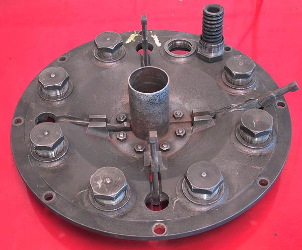
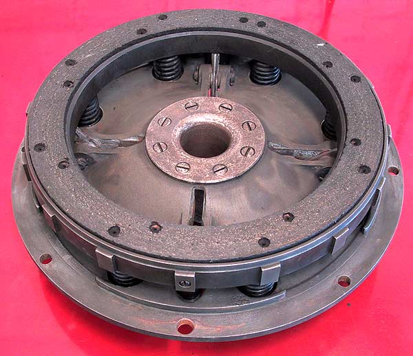
The forward (towards engine) face of the pressure plate cover showing the inner ends of the springs and the toggles on the actuating levers. The springs are restrained from full extension by a threaded shaft screwed into the end caps. The caps shown here fit into the rebates in the ring shown in the previous photograph.
Careful examination of this picture shows that the wear-face of the toggles (here positioned at 3 and 6 o'clock) have been worn flat. Further investigation and rectification will be needed before re-assembly.
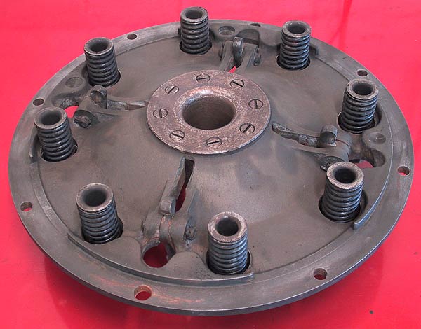
The outside of the pressure plate cover (ie facing the gearbox). The carrier ring has been disconnected so that the levers can be shown. Note that the outer spring caps are threaded and screw into the main casting. This system allows the pressure to be removed from the assemble for easier assembly and disassembly.
The tube from the driven disc runs inside the tube shown here: the pressure plate tube runs inside the clutch release bearing that is mounted in the gearbox bell housing.
The complete pressure plate viewed from the inside.
The foregoing analysis of the state of this clutch assembly leads to the conclusion that the only possible cause for the clutch slip must be that the compression springs have lost their temper (a little like their owner).
The springs will be replaced whereas the owner will not.