 The
Forgotten Engine - click the icon to find out more !
The
Forgotten Engine - click the icon to find out more !The
Forgotten Engine - click the icon to find out more !
The following table gives a breakdown of the time spent on rebuilding the engine for chassis 3CP196. The first part of the table is accurate to, the nearest half-hour per day, and represents the amount of time actually 'hands-on' with dirty fingernails. The second part of the table is a prudent approximation of the additional time spent in research, sourcing parts and other non-productive, but nevertheless necessary, activities associated with the project.
| PROJECT PERIOD - 31st October 2001 to 7th February 2003 | |
| Part 1 - actual time spent working on the engine | |
| Removing front bodywork and removing the engine from the chassis | 30 |
| Dismantling the engine | 111 |
| Specialist engineering time on the crankshaft and associated components | 255 |
| Cleaning sub-assemblies, overhauling ancillaries and repainting where appropriate | 351 |
| Re-assembling the engine | 104 |
| Re-installing the engine and assembling the bodywork | 112 |
| Holding breath to see if it works... | an eternity |
| Actual total working hours |
963 |
| Part 2 - approximation of time spent controlling the project | |
| Photography editing | 150 |
| Technical research, sourcing parts, fetching and carrying | 300 |
| Building and maintaining this web site | 500 |
| Estimated total support hours |
950 |
| Overall project length |
1913 |
| At a work rate of 8 hours a day, 5 days a week, this represents 48 man-weeks. | |
The Phantom III engine has a V12 configuration. The two cylinder banks are denoted A and B; the A bank is on the right hand side of the car when viewed from the driving seat.
| Description | Spec. | Imp. | US | Metric |
| Coolant | 46 pints | 28.8qts | 26 ltrs | |
| Engine oil ***(see footnote 1) | 20w50 | 22 pints | 13.8qts | 12.5 ltrs |
| Gearbox oil | SAE40 | 8 pints | 5 qts | 4.5 ltrs |
| Rear axle oil | EP90 | 2 pints | 1.25 qts | 1.1ltrs |
| Front dampers (each side) | SAE20 | 4 pints | 2.5 qts | 2.25 ltrs |
| Engine configuration | V12 | |||
| Firing order | A1:B6:A4:B3:A2:B5:A6:B1:A3:B4:A5:B2 | |||
| Bore | 3.25" | 3.25" | 82.5mm | |
| Stroke | 4.5" | 4.5" | 114mm | |
| Engine displacement | 448cu" | 448cu" | 7340cc | |
| Spark plug gap (24 plugs - 2 per cylinder) | 0.025" | 0.025" | 0.64mm | |
| Ignition points gap (4 sets - 2 per distributor) | 0.030" | 0.030" | 0.76mm | |
| Distributors (2 items - A & B - each
firing 12 plugs)
A distributor feeds all exhaust-side spark plugs B distributor feeds all inlet-side spark plugs |
||||
| Ignition timing - hydraulic tappet engines
***(see footnote 2)
A distributor to the AAI flywheel mark (13degrees BTDC) B distributor to the BAI flywheel mark (15 degrees BTDC) |
||||
| Ignition timing - solid tappet engines
A & B distributors to the BAI flywheel mark (15 deg. BTDC) |
||||
| Valve rocker gap - A/B/C series with hydraulic tappet actuation (0.020" flywheel marking) | I&E | 0.015" | 0.015" | 0.38mm |
| Valve rocker gap - D series plus cars with solid tappet conversion (0.030" flywheel marking) | I&E | 0.010" | 0.010" | 0.25mm |
| Footnotes 1) When the engine oil is drained approximately 3 pints of old oil is retained in the camshaft well and oil pump drive-shaft cavity. 2) Engines with hydraulic tappets may have both distributors set to the BAI mark at the owner's discretion. |
||||
The 6 big end journals are paired to give a balanced loading in operation. Viewed from the front, the groupings are, in rotation order, 1&6, 2&5, 3&4. By studying the schematics it will be seen that the effect is to move the loading back and forth along the crankshaft during the firing sequence.
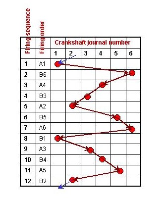
The firing order, in its more usual format, is shown in the table below :-
| A bank | 1 | 4 | 2 | 6 | 3 | 5 | ||||||
| B bank | 6 | 3 | 5 | 1 | 4 | 2 |
The following table gives the sequence for adjusting the tappets on both cylinder banks. Each bank can be adjusted with two revolutions of the crankshaft; two tappets are adjusted at each position. It is easier to turn the engine over, using the starting handle, if the exhaust-side spark plugs are removed.
The table is constructed using the number 1 valve on each bank as the starting point - the valves are numbered consecutively from the front of the engine. Rotate the crankshaft until the number 1 valve is fully open (rocker at maximum deflection) and then rotate the crankshaft through 360 degrees. The camshaft is geared to operate at half crankshaft speed so this operation will position the cam lobe 180 degrees off the open position. For each subsequent adjustment position it is necessary to rotate the crankshaft approximately 120 degrees. Absolute accuracy after the initial set-up is not crucial as the valves are 'off-lobe and gapped' for roughly 240 degrees of camshaft rotation.
| Sequence | Valve # | I or E | Cylinder | Degrees of crank rotation |
| 1 | 1 | I | 1 | 0 (set-up) |
| 3 | E | 2 | - | |
| 2 | 8 | I | 4 | +120 (=120) |
| 11 | E | 6 | - | |
| 3 | 4 | I | 2 | +120 (=240) |
| 6 | E | 3 | - | |
| 4 | 12 | I | 6 | +120 (=360) |
| 10 | E | 5 | - | |
| 5 | 5 | I | 3 | +120 (=480) |
| 2 | E | 1 | - | |
| 6 | 9 | I | 5 | +120 (=600) |
| 7 | E | 4 | - |