 The
Forgotten Engine - click the icon to find out more !
The
Forgotten Engine - click the icon to find out more !The
Forgotten Engine - click the icon to find out more !
Overcoming fuel starvation (20, 20/25, PI &PII)
Flushing the cooling system - PIII
Carburettor accelerator pump repair (PIII & Wraith)
DISCLAIMER - Please note that the following articles and procedures are made available for information purposes only. All methods have been used by the author and have provided satisfactory results. The author takes no responsibility for any loss or damage resulting from the application of these procedures by any third party.
This is a total loss lubrication system which means that the oil is expected to end up on the floor. Excessive outpouring indicates wear and should be investigated. However, too many people try to achieve an oil-dry chassis; this is completely contrary to the design philosophy of the system.
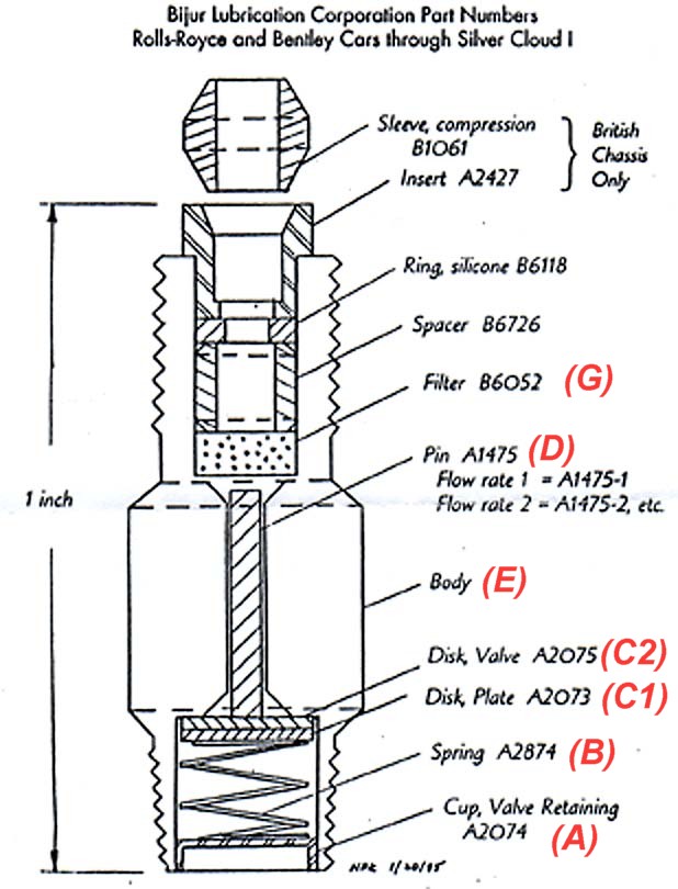
The Diagram of Chassis Lubrication System in the Owner's Handbook shows the position , type and location of the drip plugs for each chassis series. The type and flow rate for each plug is stamped on one of the nut flats (eg ZS2); the higher the number, the greater the flow of oil. The letters describe the design type as shown below :-
ZS Straight (in line)
ZE Elbow (having a 90o bend - the filters are on the inlet side and the valve is round the corner)
ZT Straight but with no valve mechanism, just a specific diameter hole
Check that there is oil in the reservoir, system filters are clean and there are no breaks or kinks in the pipes. It is most important that plugs of the correct rating are in the appropriate lubrication points. The following list is a resume of the problems encountered on various cars.
Visually inspect the junction of the moving parts being supplied by the plug. If there is no sign of oil then it is not being lubricated. Some pipework passes inside the brake drums so any sign of oil dripping from inside the backplates means there is either a broken pipe or a leaking union.
Clean the exterior of the union and disconnect the supply pipe from the plug. Press the pump lever and ascertain that oil is reaching the plug. Remove the plug and attach to the pipe union and press the pump; even if oil eventually drips through the plug may be partially blocked.
Thanks and acknowledgements go to :-
Neal Kirkam for the diagram which was originally published in Flying Lady issue 95-3.
Gil Fuqua for supplying the pin data and contact address for spare parts.
The following table shows the pin data and part numbers for ordering. All other parts are also available from the manufacturers.
| Pin # | Diameter " | Bijur part # | ||
| 00 | .0501 | A1475-00 | ||
| 0 | .0497 | A1475-0 | ||
| 1 | .0490 | A1475-1 | ||
| 2 | .0480 | A1475-2 | ||
| 3 | .0468 | A1475-3 | ||
| 4 | .0448 | A1475-4 |
Fuel vaporisation seems to be one of those problems that afflicts only the few. It matters not whether one drives a Small Horse, a Phantom or a Bentley. Readers who scoff at the poor incompetents who obviously fail to care properly for their cars may terminate here and skip onto the next article. Those sufferers who know the frustration and embarrassment may now learn the secret.
Since acquiring The Honourable, my 1933 20/25 (GGA27), I have tried just about every remedy known to just about every expert in the Royce fraternity. Propping open the shutters on the radiator seemed the only sure fire way of overcoming the vapours. The down side to this activity being an engine that runs at about 50oC; not too bad in the warm summer months but definitely receiving a cool reception when motoring at any other time of the year.
Let me give you some background information. In attempting to overcome this malaise I have :-
Summer and winter, unless the shutters were propped fully open, vapour lock occurred at precisely 74oC. This would happen even when the ambient air temperature was close to freezing.
The answer is to clean out your fuel filter again. Not a quick swill through with petrol and the air hose but back to shiny metal. The 20/25 filter comprises one thick perforated circular top plate and one solid base plate that clamp between them 62 thin disks. Each disk is 1.532 inches in diameter (1 17/32 "), is shaped like a three spoked wagon wheel and has 24 small radial ridges on one face of the rim. Nominal disk thickness 0.020 inches with a ridge height of 0.002. Petrol is introduced to the outer face of the filter and then percolates between the disks to the outlet in the centre; all foreign bodies being left behind in the bowl. With the passage of time the disks become coated in a petrol varnish in the lands between the ridges. When the varnish becomes thick enough it is capable of expanding sufficiently to block the transfer of petrol and give all the symptoms of vapour lock.
Dismantle the filter cylinder completely. Abrasive cleaning of the disks is not an option - all that happens is one ends up with very thin flat rings. I tried every solvent in my workshop, plus most domestic ones in the kitchen. I even tried vinegar, sauces and Coke in desperation yet the varnish refused to budge. In a flash of inspiration (probably desperation) I tried lemon juice and, hey-presto, small brown clouds started lifting from the plates. Leave the ingredients marinating over night, stirring occasionally, and by breakfast there will be a bowl of shining rings in a rich brown gravy.
Wash down, re-assemble and your fuel starvation problems will have disappeared.
The problem with sedimentation occurs in all old engines. Certain proposals in the following section may apply to other models but the PIII V12 aluminium engine blocks suffer from specific problems that are addressed below. Much has been written on this topic with solutions ranging from simple back flushing of the system through to cutting out side sections of the block and then attaching cover plates. The ultimate resolution is an engine strip down and radiator re-core. Where the owner does not wish to go to these lengths at the present time there are a couple of tricks that may help alleviate the symptoms.
Sturgene is far more searching than proprietary flushing compounds. If you wish to test this claim, flush the system first with a recognised flushing compound and then try this method - see what else is blown out.
Not wishing to part with any more money I applied the thinking cap. The upshot being that I have repaired the piston at no direct cost and in less than a couple of hours including travelling time.
Description :-
The leather seal has the profile of a shallow cup. Diameter at the base is 23/32"
external and 5/8" internal with a 1/2" hole in the centre. The upstand (seal
face) is 3/16" external height. As shown in Tom Clarke's photograph, the seal lip is
forced outwards, against the wall of the pump bore, by the insertion of the circular coil
spring.
The plunger is a shaped metal rod with a 5/8" disk at its lower end. The leather cup was placed over the disk (like an inverted cup) and then trapped in place by a second sleeve and disk that was crimped onto the plunger rod. Hence the reason why it cannot be dismantled.
Method :-
Remove the circular coil spring
Tear away the remaining leather
Clean out the groove between the two retaining disks. The gap is approximately 1/32". I used the cutting disk on a Dremel electrical hand tool (SB Tool Products of Chicago, Ill.). The disk is conveniently .027" thick.
Obtain an off-cut of new shoe leather used for re-soling shoes. Mine cost me nothing from the local cobbler. The leather is extremely hard and happens to be exactly 3/16" thick.
Use a 1 1/8" tank cutter to form a blank disk of leather.
Using a lathe, turn-up a mandrel of the same diameters (the centre lug being used to centralise the disk).
Stick the leather onto the mandrel using super glue.
Using a sharp lathe tool and a turning speed of at least 1000rpm turn down the disk and mandril to 23/32".
Adjust the tool post and machine out the centre of the disk to a depth of 5/32" (leaving 1/32" to fit between the clamping plates). Wall thickness of roughly 1/32" should be left to form the seal face. It will be found that the wall naturally spreads from the tool as the machined depth increases.
Drill out the centre of the seal to 1/2" diameter.
Remove the seal from the mandrel. TOTAL PRODUCTION TIME, SO FAR, IS ABOUT 10 MINUTES
Soak the seal in warm water for a few seconds. The leather becomes very supple.
Gently stretch the seal over the plunger, easing the base into the slot. A small, thin, blunt blade is useful to force the leather fully home.
Dry the seal and it shrinks to a tight fit.
Gently peen or punch the disk so that it grips the leather.
Re-insert the coil spring.
It will be necessary to test fit the seal in the pump bore. I found that slight relieving with wet and dry paper was necessary to obtain a good sliding fit when the seal was petrol soaked.
Hey-presto! It works.