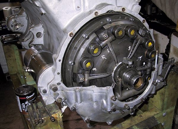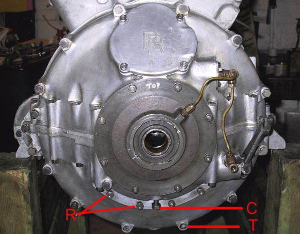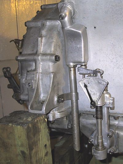

The upper casing in place. Why it was felt necessary to use 15 through-bolts and 8 vertical bolts I can not imagine. The end plate with 'top' marked on its top contains the support bearing for the clutch output shaft. The one-shot piping is feeding the support bearing, clutch release bearing and clutch cross-shaft.
The studs and nuts marked 'R', plus the matching pair on the right, are to attach the rear engine mounting that may only be installed once the engine is mounted in the frame. 'C' is the mounting point for the engine steady bar that connects to the chassis cruciform. 'T', and its partner to the left, are the mounting holes for the bolts supporting the triangular plate that connects the bracing tube for the gearbox.
