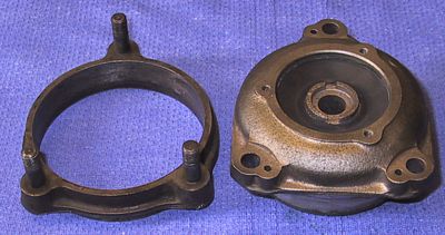
Well now, I came to this topic purely because it meant that I could empty my first box of bits. Newly moulded front engine mountings - no problem! The first one slipped straight into the support ring beautifully - but the other one did not.
I can only image how the problem was caused but the second outer ring was not circular. I jigged it up in the lathe and lightly cut the inner circumference to establish the points of distortion. Having approximately re-profiled the support in a vice it was then a matter of patience, engineers blue, grinding and emery paper to get back to a proper fit. This method was quicker than risking radial distortion in the lathe chuck or setting up the face-plate.
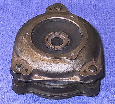
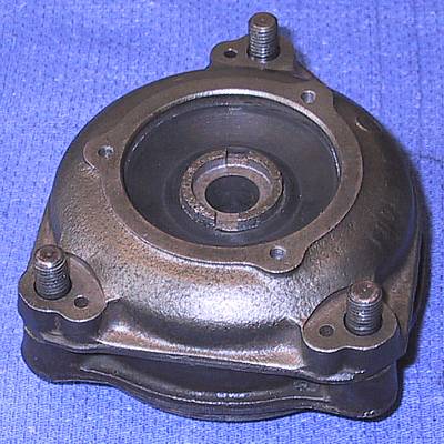
After - after a gentle push.
IMPORTANT - before assembling the mountings to the foot check that the small hole in the metal base of the rubberised section will fit easily over the pin on the chassis support bracket. I found that the nearside pin on my chassis bracket had been replaced by one of larger diameter - the hole in the base of the rubberised section had, therefore, to be enlarged to accommodate the modification.
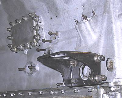
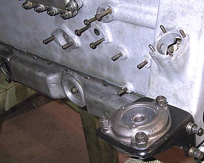
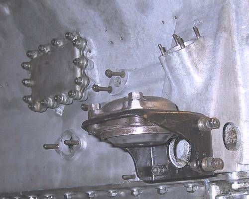
A view from below. In the centre of the rubber cone is the metal core that sits on the circular foot attached to the chassis. The mounting bolt passes through a locating spacer and then through the middle of the block to screw into the chassis foot.
The two forward facing bolts are for the engine friction damper.