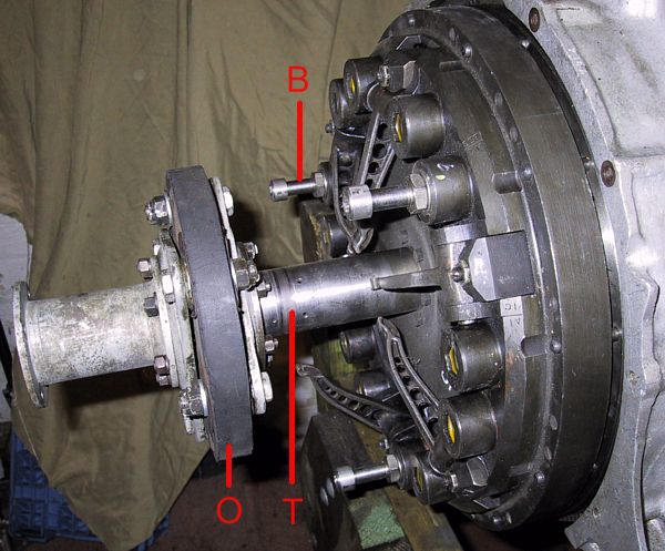
Clutch cover plate loosely fitted onto the flywheel studs - clutch plate already in place. Note the three nuts and bolts ('B') that are need to pull the pressure plate far enough off the flywheel to allow assembly.
The tube 'T' is attached to the clutch cover and supports the release bearing. The output shaft (shown here at 'O' and connected to the flexible coupling and prop shaft) is a very convenient clutch centralising tool.
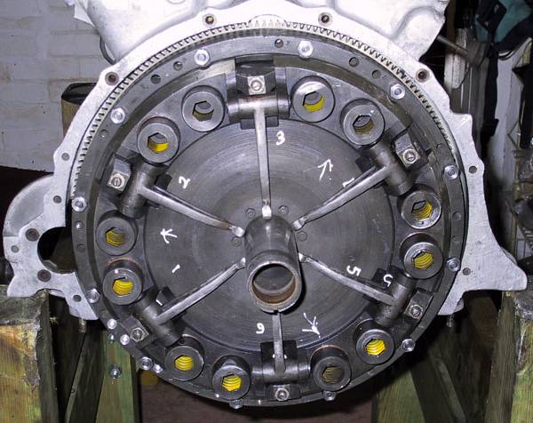
The flywheel and pressure plate cover are both marked for A1 TDC - so the marks must obviously be lined up when assembling.