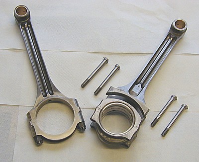
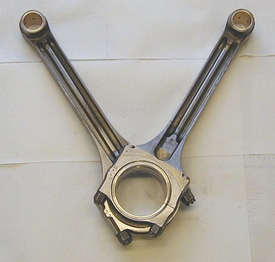
This picture shows the con rod pair as it would sit in the engine. Note the big end shells - there are two sets seated side-by-side and then machined to width.
Original specification for the con rods was for white metal on both the big end and on the blade rod housing. Some time in the past this set of rods had been converted to Halls metal shells on the big ends (as on 'D' series engines) but had been left as white metal on the blade (outer) surface. As has been recounted earlier in the diary, the Halls metal conversion required boring out the big end housing to 2.400". The Halls metal shells are no longer available, thankfully, so the big end shells were replaced by placing two sets of modified Ford shells in each bearing block. The blade rod shells were available 'off the shelf' from Rolls-Royce. (See 26th July 2002 for details.)
All very straight forward; EXCEPT that when the white metal was removed it was found that the original machining was not good enough to take the outer shells. The big end blocks had to be jigged, ground concentric on both inner and outer surfaces, hard chromed to replace the missing material and then re-ground back to tolerance. Having achieved this, the blocks had to be machined for the shell tangs and modified oil hole positioning.
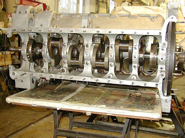
Crank installed with new main bearings.
It is IMPORTANT that the timing idler gear and housing are installed at this stage as it gets a bit congested inside the block later on.
It is also IMPORTANT that the rear camshaft bearing is installed BEFORE fitting the flywheel.