Rolls-Royce 20/25 - dismantle dynamo drive
All photographs on this page are taken with the engine canted over at roughly 80 degrees to the right.
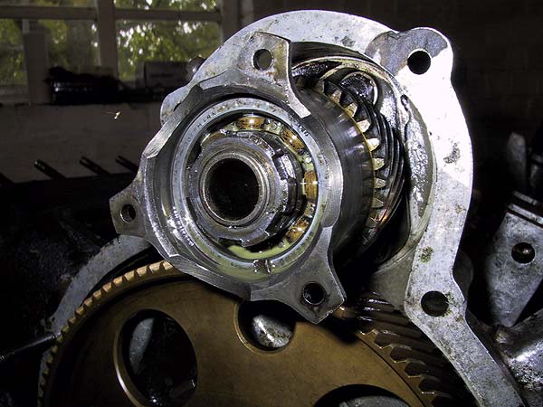 |
The dynamo drive, after removal of the output shaft, showing the serrated nut that retains the bearing and pinion. |
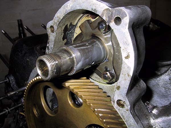 |
The outer spindle is bolted to the housing; the inner bearing carrier (with threaded end) can now be pushed out.
|
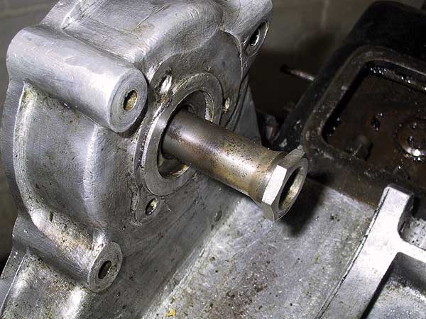 |
The bearing carrier tube is an machined fit into the rear face of the pinion spindle. It is pushed out towards the rear of the engine.
|
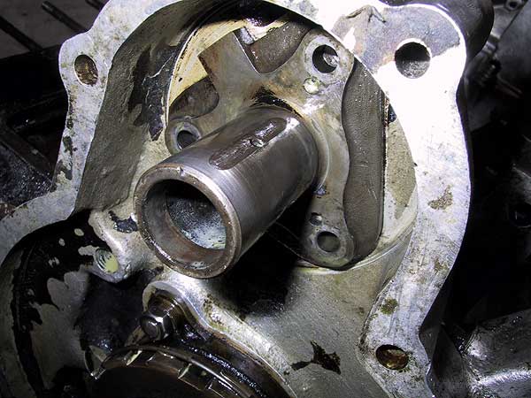 |
The oil supply holes and grooves are clearly visible. With the bolts removed the spindle may be tapped out of the casting.
|
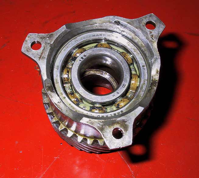 |
Pinion and bearing seen from the front. Note the spacing ring (shown offset) that is between the bearing and pinion body.
|
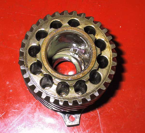 |
Pinion rear view: again showing the spacer. |