Rolls-Royce 20/25 - main bearings
 |
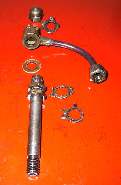
Each main bearing receives its oil feed from the main supply pipe via this convoluted set of connections. The components are laid out in their relative positions. Note the internal tangs on the middle tab washer - see next picture. The stand pipe for bearings numbered 1 to 3 and 5 to 7 are threaded at their bases. See below for the #4 pipe. |
 |
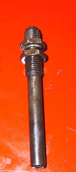
The number 4 stand pipe is threaded at its top. Note the slot cut into the upper union thread. There are two slots, which act to retain the tab washer used to lock the pipe union nut and its lock-nut.
|
 |
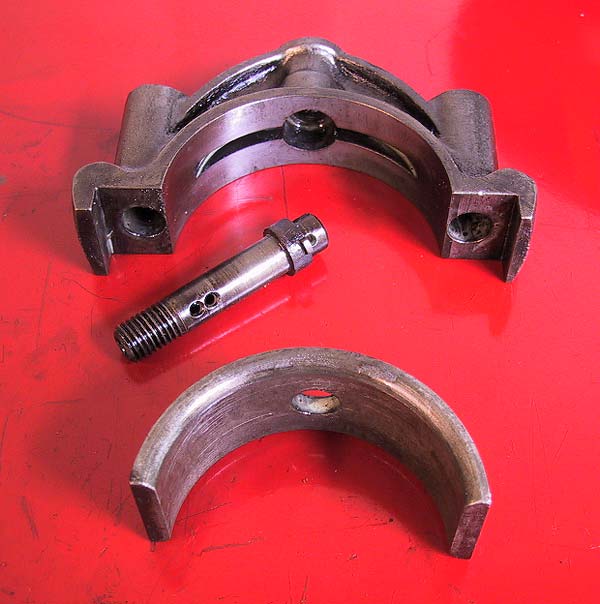
The main bearing caps have a separate banjo bolt that is located by tangs that fit into the oil channel. |
 |
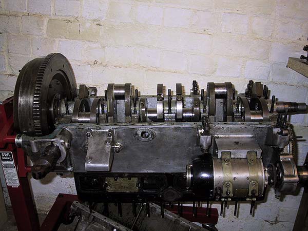
Flywheel ready for lifting out of the crankcase. |