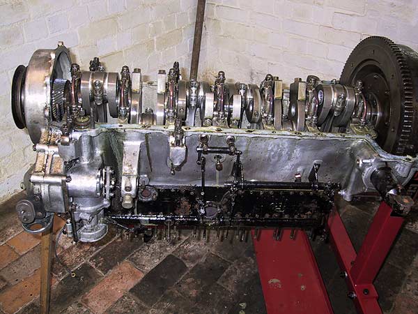
Sump removed - it looks so impressive.
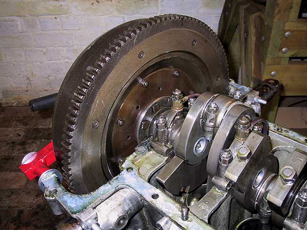
Flywheel - inside view. The holes are where the carrier ring for the clutch friction disc is attached.
Note the main bearing caps and oil supply pipes. Two sludge trap caps are visible.
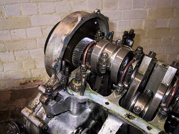
Front view showing the inner face of the crankshaft damper and its drive pinion. The splined end of the oil pump drive shaft is visible. The other end of this shaft drives the distributor.
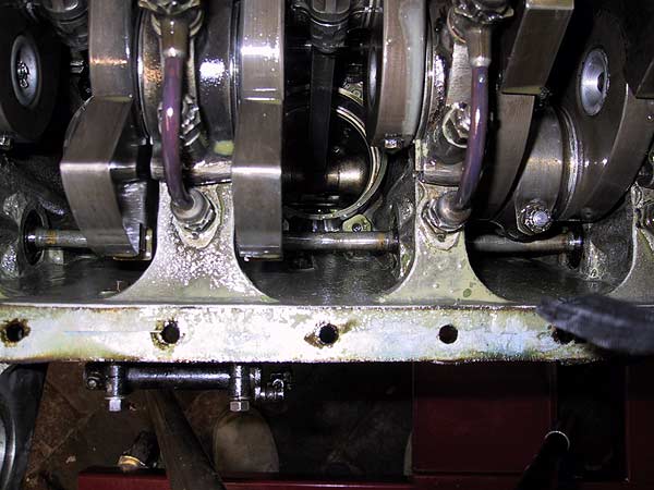
Looking into the driver's (right) side of the engine from underneath.
Centre-view is the underside of #5 piston and con rod. Across the bottom of the picture is the main oil supply pipe that feeds the lower main bearing pipes via drillings in the crankcase casting. Big end journals are fed through drillings in the crankshaft webs.
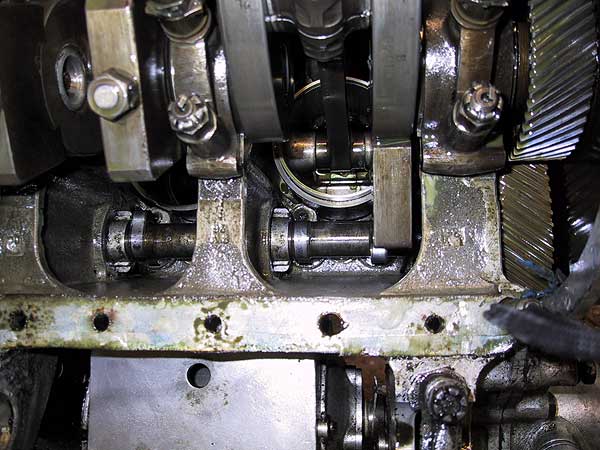
Passenger (left) side of the engine from underneath.
On the right can be seen the cam wheel (bottom of picture) and crankshaft pinion for the damper. Along the bottom of the picture is the camshaft. From the view of the left lobe it can just be discerned that the cam profile is a true pear-shape: giving a relatively rapid open and close movement of the valves. To obviate wear from this design of lobe the followers have a wheel that sits on the shaft.