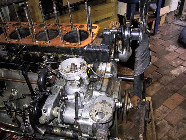
Coil removed. The original housings were held in place by two 2BA setscrews passing through the casting into the base of the coil.
Fan assembly still in place after removing the belt.
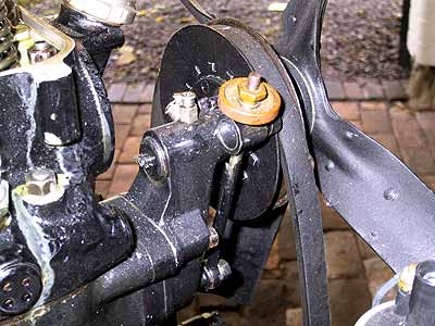
Time warp! Belt still in place; showing the adjustment mechanism slackened off and ready for removal.
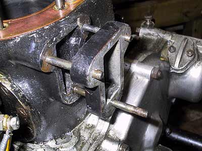
Pulley removed from the front of the cylinder block. Note the aluminium spacer used to align the top and bottom pulleys.
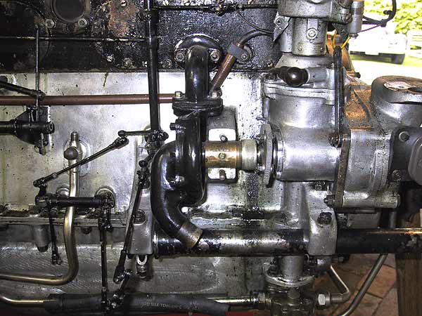
First stage of water pump removal - disconnect the aluminium bridge piece.
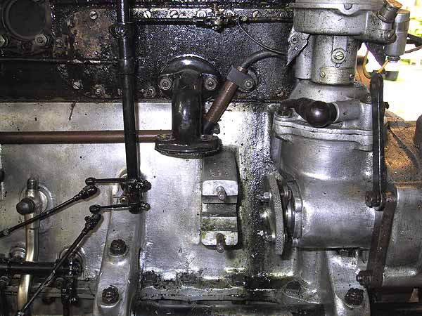
Separate the pump from the upper outlet pipe and pull out from the seat and splined drive.
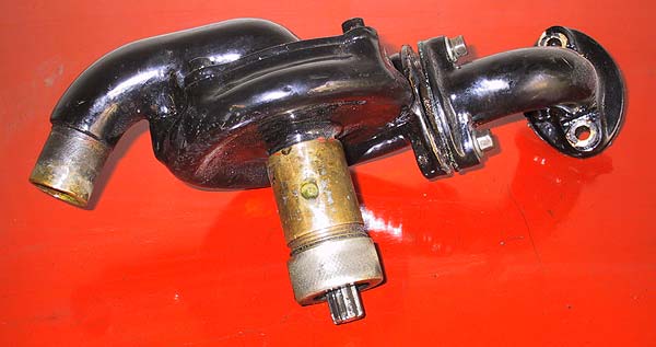
Water enters stage left (from radiator bottom hose) and exits to the block, right.
The hole in the middle of the shaft tube is where the grease cup fits. The knurled nut (bottom) on the drive shaft should only be done up hand tight.
The pump should only ever be lubricated with the correct WATER PUMP GREASE. Anything else will soften and either drain out of the pump or clog up the cooling system. Water pump grease is readily available at nominal cost - just search on the internet. Penrite is good and comes in small pots.
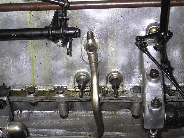
This is the main oil feed pipe into the oil gallery. The thread on the top is the take-off for the oil pressure gauge. The cap nut that holds this pipe in place (not shown) has a domed face to mate with the socket on the pipe. There is a domed sealing washer interposed between the two.
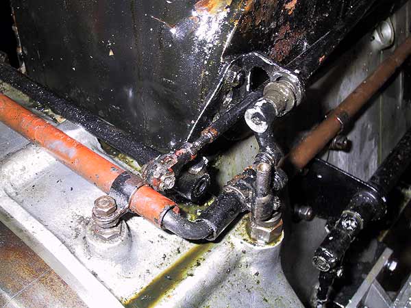
Rear right side of the block showing the remaining control rods. These usually reside just in front of the bulkhead and behind the fuel filter. It would appear that some remedial work will be required to the pivots and paintwork prior to re-installation.
These rods need removing to release the block.
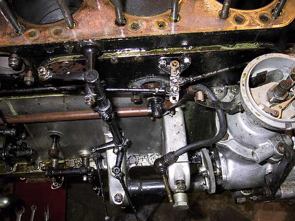
The remaining rods - they need to go back in the same places.
The magneto HT lead and pipework will also need removing.
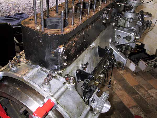
All external parts are now removed. Tappet chest bridge pieces will be left in place until the block is to be lifted off.